High-speed data connectors
Ensuring signal integrity for more data to transfer – fast and reliably
With the rise of multi-source sensing, the Internet of Things, Industry 4.0 and new interconnected ecosystems, more and more data have to be transferred quickly, reliably and securely. Ensuring signal integrity by meeting data reliability and data speed requirements is critical for engineers designing and interconnecting data-heavy applications relying on constant streams of accurate data.
Above all, at high bit rates and over long distances, effects such as noise, distortion, insertion/return losses, and crosstalks may degrade electrical signals to the point where errors occur, and a device or system fails.
Sales request
Get STEP files and product information
Our high-speed data connector solutions
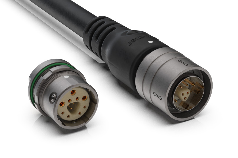
The high-speed data connector solutions from Fischer Connectors are designed and tested to high-speed data transfer protocols, offering a unique ruggedized, water-tight housing, with a choice of several locking systems:
The high-speed data connector solutions from Fischer Connectors are designed and tested to high-speed data transfer protocols, offering a unique ruggedized, water-tight housing, with a choice of several locking systems:
The high-speed data connector solutions from Fischer Connectors are designed and tested to high-speed data transfer protocols, offering a unique ruggedized, water-tight housing, with a choice of several locking systems:
Optimized data & power
- High-density miniaturization
- Unique combinations of signal and power
- Designed and tested to high-speed data transfer protocols
- USB 3.2 Gen 2, Ethernet, Audio/UHD Video
- Up to AWG 18 and 10 Amps
- 360° EMC shielding by design
Rugged and sealed
- Up to 10,000 mating cycles
- Blind mating with robust keying code
- Operating temperatures from -55 °C to +135 °C
- IP68 sealing 2m/24h mated & unmated (deeper upon request)
- IP69 (protection against intense water jets)
- Hermetic (gas tight, vacuum tight)
- High shock and vibration resistance
- High corrosion resistance (up to 1,000 hours of salt mist)
Our product range
Our product range
Our product range
 Need other features?
Our custom connector capabilities will help you meet your needs.
Learn more about high-speed data connectors
The connectivity matter
The connectivity matter
The connectivity matter
The emergence of high-speed data transmission during the past decades and the demand for greater bandwidth during the coming years are driving engineers in each part of the connectivity system, from software developers to cable-connector providers, to optimize their products while ensuring they meet the new requirements.
Balanced cabling performance is defined by a set of multiples parameters. The most relevant are insertion loss, return loss (reflection), near-end crosstalk (NEXT), and far-end crosstalk (FEXT).
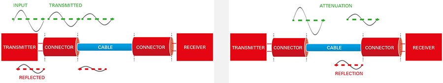
Also called attenuation, insertion loss is the amount of energy that a signal loses when travelling along a cable link.
Also called attenuation, insertion loss is the amount of energy that a signal loses when travelling along a cable link.
Also called attenuation, insertion loss is the amount of energy that a signal loses when travelling along a cable link.
The insertion loss of a cable evidently depends on the length of cable – the longer the cable, the higher the insertion loss. Insertion loss is also caused by any connection points along a cable link (i.e., within connectors and splices).
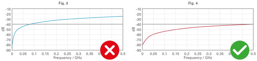
Like insertion loss, return loss is another important parameter in both copper and fiber systems. Rather than measuring the amount of loss over a link, return loss measures the amount of power injected from the source compared to the amount reflected back towards the source. In summary, return loss is the loss of signal power due to signal reflection or return by a discontinuity in a fiber optic link or a transmission line impedance mismatch.
Reflection loss is the most important mechanism of signal loss in the high-speed data connector, while attenuation (insertion loss) is the main mechanism of loss in the cable itself. To ensure the best performance of a link, both the return loss and the insertion loss must be optimized and included in the link budget calculations.
The insertion loss of a cable evidently depends on the length of cable – the longer the cable, the higher the insertion loss. Insertion loss is also caused by any connection points along a cable link (i.e., within connectors and splices).
Like insertion loss, return loss is another important parameter in both copper and fiber systems. Rather than measuring the amount of loss over a link, return loss measures the amount of power injected from the source compared to the amount reflected back towards the source. In summary, return loss is the loss of signal power due to signal reflection or return by a discontinuity in a fiber optic link or a transmission line impedance mismatch.
Reflection loss is the most important mechanism of signal loss in the high-speed data connector, while attenuation (insertion loss) is the main mechanism of loss in the cable itself. To ensure the best performance of a link, both the return loss and the insertion loss must be optimized and included in the link budget calculations.
High-speed data transmission and signal integrity
Interconnect designs aimed at providing high-speed data transmission must ensure signal integrity in suppressing external radiated electromagnetic and radio frequency interferences (EMI/RFI).
To guarantee the successful transmission of data from a device’s transmitter to its receiver with high-speed, connectors and cables must be cross-optimized. The main influential parameters to consider are: connector design, cable length, cable performance (loss), and the controlled and repeatable cable assembly and potting processes above 1 Gbit/s.
In their designing and characterization process, engineers thus look after, among others, the following decisive parameters:
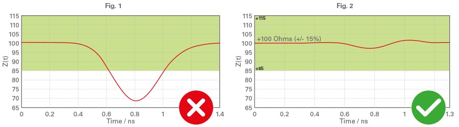
- Impedance matching (ratio of V/I or E/H): like the concept of resistance at low frequency, the concept of impedance at high frequency can be seen as the ratio of electric field to the magnetic field for a transverse electro-magnetic (TEM) wave. For a communication link, the impedance of the source, the cable-connector and the receiver must be as close as possible to ensure no loss of signal due to reflection.
In their designing and characterization process, engineers thus look after, among others, the following decisive parameters:
- Impedance matching (ratio of V/I or E/H): like the concept of resistance at low frequency, the concept of impedance at high frequency can be seen as the ratio of electric field to the magnetic field for a transverse electro-magnetic (TEM) wave. For a communication link, the impedance of the source, the cable-connector and the receiver must be as close as possible to ensure no loss of signal due to reflection.
- Line delay: the latency of signal propagation.
- Insertion loss: the loss of signal due to dielectric or ohmic loss.
- Return loss: the loss of signal power due to signal reflection or return by a discontinuity in a fiber-optic link or a transmission line.
- Crosstalk: in some communication links, there are some parallel links that must work simultaneously. The problem arises where the electromagnetic field from one link couples to another field and causes interference. Two well-known parameters in this respect are near-end crosstalk (NEXT) and far-end crosstalk (FEXT).
- EMC shielding: electromagnetic compatibility (EMC) shielding is a way of protecting a sensitive signal from external electromagnetic signals, preventing electromagnetic interference (EMI) or radio frequency interference (RFI) from impacting sensitive electronics and vice versa.
To guarantee the performance of a communication, all the components of a link including electronics and cable-connectors must comply with the relevant standards, and a component-level compliance procedure is here highly recommended.
Note that in lots of scenarios, the application deviates from the setup of a standard. In those cases, you need to study the full physical layer of a link as a whole – what we call system-level testing. This includes performing SerDes simulations (serializer/deserializer) and drawing eye-diagrams and BER timing curves (bit error rate) to analyze the jitter budget.
Data protocols
Data protocols provide the normative values of data transmission parameters (insertion loss, return loss, crosstalk, noise) to ensure the compatibility of the various components of a system – transmitter, receiver, cable, connector – so that they can function together appropriately.
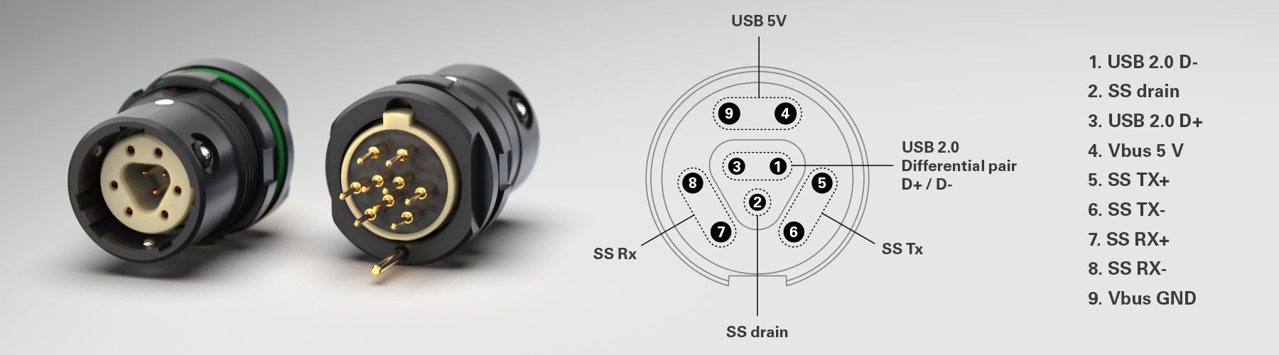
Typical protocols include Ethernet, USB, SDI, DP and Audio/UHD Video. The protocol determines the number of contacts for each connector, e.g., 4 contacts for USB 2.0., 9 for USB 3.0, 8 for Ethernet Cat 5e (1 Gbit/s), and 19 for Audio/UHD Video. Specific design rules for the high-speed data connector’s pin configuration and special materials are required for both the connector and cable to help reduce interference.
Data protocols provide the normative values of data transmission parameters (insertion loss, return loss, crosstalk, noise) to ensure the compatibility of the various components of a system – transmitter, receiver, cable, connector – so that they can function together appropriately.
Typical protocols include Ethernet, USB, SDI, DP and Audio/UHD Video. The protocol determines the number of contacts for each connector, e.g., 4 contacts for USB 2.0., 9 for USB 3.0, 8 for Ethernet Cat 5e (1 Gbit/s), and 19 for Audio/UHD Video. Specific design rules for the high-speed data connector’s pin configuration and special materials are required for both the connector and cable to help reduce interference.
| STANDARD PROTOCOL | DATA RATE | # OF CONTACTS | |
|
|
USB 2.0 | 480 Mbit/s | 4 |
|
|
USB 3.2 GEN 1 | 5 Gbit/s | 9 |
| USB 3.2 GEN 2 | 10 Gbit/s | 9 | |
|
|
Ethernet 10Base-T | 10 Mbit/s | 4 |
| Ethernet 100Base-TX | 100 Mbit/s | 4 | |
| Ethernet 1000Base-T | 1 Gbit/s | 8 | |
| Ethernet 10GBase-T | 10 Gbit/s | 8 | |
|
|
SPE 10BASE-T1 | 10 Mbit/s | 2 |
| SPE 100BASE-T1 | 100 Mbit/s | 2 | |
| SPE 1000BASE-T1 | 1 Gbit/s | 2 | |
|
|
Audio/UHD Video | 10.2 Gbit/s | 19 |
Our high-performance connectivity solutions are compatible with most popular data protocols: USB 2.0, USB 3.2 Gen 1 and Gen 2 up to 10 Gbit/s, Ethernet up to 10 Gbit/s, and Audio/UHD Video. We also provide Single Pair Ethernet solutions that can transmit data at speeds of up to 1 Gbit/s with or without Power over Data Line (PoDL), e.g., for rugged industrial applications and defense & security unmanned aerial vehicles (UAVs).
The design of both the high-speed data connector and the cable is optimized according to each data protocol used – or to a combination of protocols when your device needs high-speed multi-protocol data transmission.
Once the design has been optimized for a defined protocol, a physical connector-cable assembly prototype needs to be tested to validate the full characterization using a Vector Network Analyzer. The S-parameters of the cable assembly are measured and compared with the target values defined in the protocol specification. If one of the parameters fails, an iteration loop will be made on the design until the cable assembly fulfills all the protocol requirements – at that time, the product can be declared ‘protocol compatible’.
It might be impossible to set up a complex system using one single protocol. In that case, the solution is to use a protocol adapter or transceiver which can turn a defined protocol into another one without degrading the signal.
Single Pair Ethernet (SPE) describes the transmission of Ethernet over only one pair of twisted copper wires. In addition to data transmission via Ethernet, SPE also enables a simultaneous power supply of terminal devices via Power over Data Line (PoDL). Without the SPE technology, two pairs for Fast Ethernet (100 MB) and four pairs for Gigabit Ethernet are required to reach this result. In addition to space and weight savings with less wire, SPE can transmit data up to 10 Gbit/s. When combined with miniaturized high-speed data connectors, SPE is a network technology with revolutionary potential in the Internet of Things (IoT), the Industrial IoT (IIoT) and Industry 4.0 systems, enabling engineers to design high-density and high-speed interconnect solutions that are easy to integrate and install.
Data security
Not all data reliability issues relate to the physical environment. The need to shield high-speed data connectors and cables from environmental hazards also includes shielding them from electromagnetic interference (EMI) and radio frequency interference (RFI). These interferences can affect many sensitive electronics and cause a wide variety of issues – from a simple hiss on a communication line to the total disruption of a safety-critical signal. Shielding protects signals from being disrupted by external electromagnetic signals and prevents generated signals from interfering with surrounding components, wires, cables, and sensors.
Electromagnetic compatibility (EMC) means that a circuit has been designed with a shield that prevents such disruptions. EMC shielding refers to any method used to protect a sensitive signal from external electromagnetic signals, or to prevent a stronger signal from leaking out and interfering with surrounding electronics. This is achieved by using a metallic screen that absorbs the electromagnetic interference transmitted through the air like in a Faraday cage.
360° EMC-shielded high-speed data connectors thus play a major role in ensuring signal integrity and secure, reliable and accurate data transmission in electronic devices, equipment and systems in industries such as medical, defense and aerospace electronics, mass transit systems, industrial test and measurement, and navigation and vehicular control systems.
Cable-shield options include three types: braid, serve/spiral, and foil. The shield consists of a conductive barrier surrounding the insulated wires inside the cable. It aims to prevent the noise that is emitted from other nearby cables or electronics – and even the noise emitted from adjacent wires within a cable such as crosstalks – from disturbing or interrupting signals within the cable. It also averts EMI radiating out of the cable, thus preventing network cables from emitting detectible, discernable signals.
Data security also highly depends on encoding and data encryption. Data is encoded through the system by the signal emitter and must be ‘understood’ (or decoded) properly by the receiver in order for the data transmission to pass correctly. Data encryption ensures that the appropriate receivers are authorized to access the information.
Data security also highly depends on encoding and data encryption. Data is encoded through the system by the signal emitter and must be ‘understood’ (or decoded) properly by the receiver in order for the data transmission to pass correctly. Data encryption ensures that the appropriate receivers are authorized to access the information.
Data security also highly depends on encoding and data encryption. Data is encoded through the system by the signal emitter and must be ‘understood’ (or decoded) properly by the receiver in order for the data transmission to pass correctly. Data encryption ensures that the appropriate receivers are authorized to access the information.